Detection and compensation of laser cutting machines
Laser cutting machine uses a laser to emit a laser, which is focused into a high-power density laser beam through an optical system. The laser beam irradiates the surface of the workpiece, causing it to reach the melting or boiling point. At the same time, high-pressure gas coaxial with the beam blows away the melted or vaporized metal, thereby achieving cutting or processing of the workpiece.
Laser cutting machines have many competitive advantages in the field of sheet metal processing, such as fast cutting speed, high production efficiency, and short product production cycle. While maintaining quality, they provide users with more output per unit time, thus occupying a time advantage in market competition.
How to ensure the processing quality of laser cutting machines on the basis of fast and efficient operation has also become an important issue.
Based on the accuracy and measurement range requirements of laser cutting machines, it is difficult to guarantee and improve their accuracy solely by mechanical means; As a precision measurement instrument, Laser Interferometer can efficiently and objectively measure the positioning accuracy, repeated positioning accuracy, reverse clearance and other data of the cutting machine, and generate corresponding compensation parameters to achieve error compensation of the cutting machine, thereby improving its accuracy.

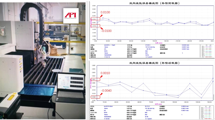
Figure 1: Using XD LASER laser interferometer to compensate for cutting machine operation site and comparison of data before and after compensation
Compensation Scheme for Pitch Error of XD LASER Laser Interferometer Cutting Machine
The use of an XD LASER laser interferometer to compensate for pitch error in a laser cutting machine can be roughly divided into four steps:
1. Machine tool origin determination
This is the basis for compensating pitch error. Different control systems have different operating methods, as long as they return to the original point normally according to the system requirements.
2. Measurement of pulse equivalent
Due to the influence of mechanical transmission, the pulse equivalent calculated theoretically often differs from the actual movement distance of the machine tool. In this case, direct compensation for pitch error is often not ideal. Therefore, it is recommended to first calibrate the pulse equivalent, match the number of pulse equivalent with the movement distance of the machine tool, and input the data into the corresponding parameters. After such processing, the linear accuracy of the machine tool can be improved by about one-third.
3. Determination of linear error
Using a laser interferometer for pitch error measurement, the corresponding parameters must be set before measurement and matched with the measurement program of the CNC machine tool:
-Travel range. The total stroke range to be measured is generally set to be slightly smaller than the designed stroke of the machine tool.
-Measure the interval. In theory, the smaller the measurement interval, the more accurate the results after compensation; But the smaller the measurement interval, the more points need to be measured, and the longer the time it takes. The recommended interval value is between 10mm and 100mm.
-Stay time. To adjust according to the operating speed of the machine tool and the mass inertia of the equipment, use an XD LASER laser interferometer and set a dwell time of 3-5 seconds, which can generally meet most machine tool testing requirements.
4. Import error data
Import error data based on different control systems:
-Some CNC systems can directly set the data format of the laser interferometer to the underlying data. In this case, the measurement data can be directly imported into the machine tool control system.
-If the interferometer data structure is not set in the underlying data of the CNC system, corresponding compensation data should be generated based on the control type of the CNC system and input into the screw compensation parameters of the machine tool control system.
After compensation, the linear accuracy of the machine tool can be greatly improved.

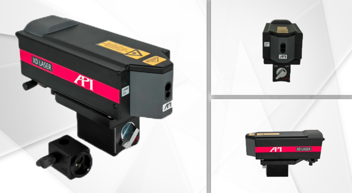
Figure 2: API Brand XD LASER Laser Interferometer
About the XD LASER series laser interferometer
The XD LASER series laser interferometer is a general equipment patented by API company and fully recognized in the industry for various machine tool testing and calibration. This equipment is convenient and efficient to use, with multiple models available in 1, 3, 5, and 6D, and offers both standard and precision versions, fully meeting the diverse requirements from manufacturing workshops to metrology laboratories; Among them, the 6D model can simultaneously measure 6 parameters during installation, including 1 positional error, 2 straightness errors, and 3 angle errors.
The testing, which usually takes several days, can be completed in just a few hours using the XD LASER six dimensional laser interferometer. The actual application results show that the work efficiency has increased by 5 times!

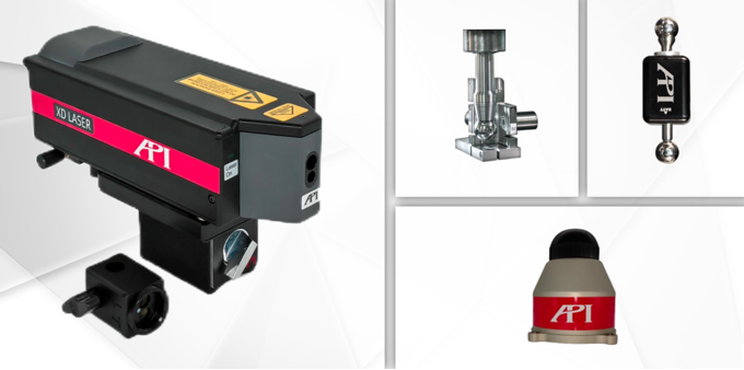
Figure 3: API MTC Machine Tool Calibration Solution
(Left side: XD LASER laser interferometer, right center: Spindlecheck Spindle Analyzer, upper right: wireless ball and rod tester, lower right: Swivelcheck angular pendulum tester)
API MTC Machine Tool Calibration Efficient Solution
Based on in-depth research on machine tool errors and nearly half a century of technological accumulation, API MTC (Machine Tool Calibration) machine tool inspection expert level comprehensive solution has been created; The plan consists of various efficient machine tool detection and calibration equipment:
-XD series laser interferometer: perfectly solves the problem of 21 parameter errors.
-Swivelcheck Angle Pendulum Checker: Solves all angle error issues of machine tools containing ABC angles.
-Spindlecheck spindle analyzer: Real time monitoring and analysis of spindle dynamic and thermal deformation errors.
-Ball and stick tester: Diagnose CNC dynamic and static accuracy.
-VEC spatial error compensation technology: enables large multi axis machine tools to achieve more than four times the accuracy improvement.
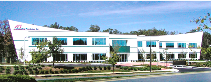
Figure 4: API Company Headquarters Building (Maryland, USA)
About API
The American Automated Precision Engineering Company (API) was founded in 1987 and is headquartered in Rockwell City, Maryland, USA. Since its establishment, API Company has always been committed to the research and development and production of precision measurement instruments and high-performance sensors in the field of mechanical manufacturing. Its products have been widely used in advanced manufacturing fields in the United States and countries around the world, and are in a leading position in high-precision standards for coordinate measurement and machine tool performance testing. API Company has an experienced and capable team of engineers who continuously develop advanced and innovative products to meet the rapidly developing industrial technology needs. API Corporation is an active participant and key technology partner in many projects of the US federal government, enterprises, and scientific research. The achievements achieved so far have earned it a high reputation in the field of international precision measurement.


